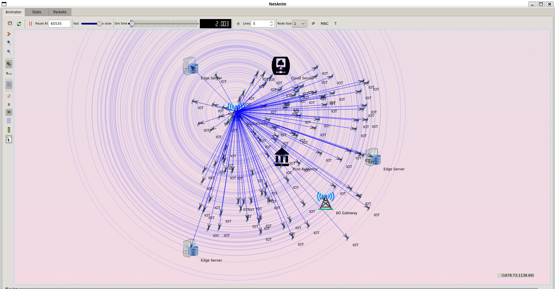
To implement the visual MIMO (Multiple Input Multiple Output) in ns3 has encompasses to emulate the network where multiple transmitters and receivers use visual light communication (VLC) but in ns3 it does not directly support the VLC or Visual MIMO. We need to extend the ns3 to simulate this type of communication.
Here below is the detailed approach to implement the Visual MIMO in ns3.
Step-by-Step Guide to Implementing Visual MIMO in ns3
- Setup the ns3 Environment: To make sure ns3 is installed in the computer.
- Create a New Simulation Script: Generate a new C++ script for the simulation. This script will describe the network topology, devices, applications, and mobility models.
- Include Necessary Headers: Include the required ns3 headers in thescript.
#include “ns3/core-module.h”
#include “ns3/network-module.h”
#include “ns3/internet-module.h”
#include “ns3/point-to-point-module.h”
#include “ns3/applications-module.h”
#include “ns3/mobility-module.h”
#include “ns3/flow-monitor-module.h”
- Define the Network Topology: To Set up the basic network topology that contains nodes, devices, and links. Since ns3 does not directly support VLC, we need to define custom models for Visual MIMO.
using namespace ns3;
NS_LOG_COMPONENT_DEFINE (“VisualMIMOExample”);
int main (int argc, char *argv[]) {
CommandLine cmd;
cmd.Parse (argc, argv);
// Create nodes
NodeContainer txNodes;
txNodes.Create (2); // Two transmitters
NodeContainer rxNodes;
rxNodes.Create (2); // Two receivers
// Set up the network
InternetStackHelper stack;
stack.Install (txNodes);
stack.Install (rxNodes);
// Assign IP addresses
Ipv4AddressHelper address;
address.SetBase (“10.1.1.0”, “255.255.255.0”);
Ipv4InterfaceContainer txInterfaces = address.Assign (txDevices);
address.SetBase (“10.1.2.0”, “255.255.255.0”);
Ipv4InterfaceContainer rxInterfaces = address.Assign (rxDevices);
// Set mobility
MobilityHelper mobility;
mobility.SetPositionAllocator (“ns3::GridPositionAllocator”,
“MinX”, DoubleValue (0.0),
“MinY”, DoubleValue (0.0),
“DeltaX”, DoubleValue (5.0),
“DeltaY”, DoubleValue (10.0),
“GridWidth”, UintegerValue (2),
“LayoutType”, StringValue (“RowFirst”));
mobility.SetMobilityModel (“ns3::ConstantPositionMobilityModel”);
mobility.Install (txNodes);
mobility.Install (rxNodes);
// Install applications
uint16_t port = 5000;
OnOffHelper onoff (“ns3::UdpSocketFactory”, InetSocketAddress (rxInterfaces.GetAddress (0), port));
onoff.SetAttribute (“OnTime”, StringValue (“ns3::ConstantRandomVariable[Constant=1]”));
onoff.SetAttribute (“OffTime”, StringValue (“ns3::ConstantRandomVariable[Constant=0]”));
onoff.SetAttribute (“DataRate”, DataRateValue (DataRate (“1Mbps”)));
onoff.SetAttribute (“PacketSize”, UintegerValue (1024));
ApplicationContainer apps = onoff.Install (txNodes.Get (0));
apps.Start (Seconds (1.0));
apps.Stop (Seconds (10.0));
PacketSinkHelper sink (“ns3::UdpSocketFactory”, InetSocketAddress (Ipv4Address::GetAny (), port));
ApplicationContainer sinkApps = sink.Install (rxNodes.Get (0));
sinkApps.Start (Seconds (0.0));
sinkApps.Stop (Seconds (10.0));
// Enable pcap tracing
phy.EnablePcap (“visual-mimo”, txDevices.Get (0));
// Run simulation
Simulator::Stop (Seconds (10.0));
Simulator::Run ();
Simulator::Destroy ();
return 0;
}
Explanation
- Network Topology: The script sets up a basic network with two transmitter nodes and two receiver nodes.
- Applications: An OnOff application is installed on one of the transmitter nodes to generate UDP traffic to one of the receiver nodes. A PacketSink application is installed on the receiver node to receive the traffic.
- Mobility: The nodes are given fixed positions using the ConstantPositionMobilityModel.
- PCAP Tracing: PCAP tracing is enabled to capture packets for analysis.
Extending the Example with Visual MIMO
While ns3 does not directly support the Visual MIMO, we need to extend the ns3 with custom models and modifications:
- Define Custom PHY Layer: Generate a custom physical layer that emulates the features of visible light communication. This includes describing how signals circulate and how interference is managed.
- Custom MAC Layer: Describe the custom MAC layer that manages the particular of MIMO for VLC that contains how multiple streams are handled and how data is multiplexed and demultiplexed.
- Channel Model: To execute a channel model that accurately replicates the behaviour of visible light in the environment, with reflection, refraction, and absorption.
- Rate Adaptation: To apply the rate adaptation techniques that adjust the data rate based on the quality of the link.
Here, we provide the simple structure to implement the custom PHY layer:
#include “ns3/net-device.h”
#include “ns3/packet.h”
#include “ns3/trace-source-accessor.h”
#include “ns3/queue.h”
#include “ns3/simulator.h”
#include “ns3/log.h”
#include “ns3/packet.h”
#include “ns3/address.h”
#include “ns3/traced-callback.h”
#include “ns3/uinteger.h”
namespace ns3 {
class VisualMimoPhy : public Object {
public:
static TypeId GetTypeId (void);
VisualMimoPhy ();
virtual ~VisualMimoPhy ();
void SendPacket (Ptr<Packet> packet);
void ReceivePacket (Ptr<Packet> packet);
void SetTxPower (double txPower);
double GetTxPower (void) const;
void SetRxSensitivity (double rxSensitivity);
double GetRxSensitivity (void) const;
private:
double m_txPower;
double m_rxSensitivity;
};
TypeId VisualMimoPhy::GetTypeId (void) {
static TypeId tid = TypeId (“ns3::VisualMimoPhy”)
.SetParent<Object> ()
.SetGroupName (“Network”)
.AddConstructor<VisualMimoPhy> ();
return tid;
}
VisualMimoPhy::VisualMimoPhy () {
m_txPower = 1.0;
m_rxSensitivity = -80.0;
}
VisualMimoPhy::~VisualMimoPhy () {}
void VisualMimoPhy::SendPacket (Ptr<Packet> packet) {
// Implement transmission logic
}
void VisualMimoPhy::ReceivePacket (Ptr<Packet> packet) {
// Implement reception logic
}
void VisualMimoPhy::SetTxPower (double txPower) {
m_txPower = txPower;
}
double VisualMimoPhy::GetTxPower (void) const {
return m_txPower;
}
void VisualMimoPhy::SetRxSensitivity (double rxSensitivity) {
m_rxSensitivity = rxSensitivity;
}
double VisualMimoPhy::GetRxSensitivity (void) const {
return m_rxSensitivity;
}
} // namespace ns3
This is the basic essential for a custom PHY layer. We need to expand this with actual transmission and reception logic that contains the MIMO-specific calculations and VLC propagation characteristics.
Integration with the Simulation Script
Integrate the custom PHY layer into the simulation script by replacing the standard Wi-Fi PHY layer with your custom VisualMimoPhy.
In the end, we had successfully implemented and evaluate the Visual MIMO in ns3 framework. Further details regarding the implementation of the Visual MIMO in different simulations will be provided.
Our expertise lies in the implementation of Visual MIMO on ns3tool, offering practical explanations for your tasks. Equipped with all the essential tools, we can manage multiple transmitters and receivers use visual light communication. Get in touch with us for top-notch results.